What’s up? We are going to have fun!
This is our first contest for electrical circuits. Solve the problem, submit your answers and cross your fingers to be the lucky winner!
Problem
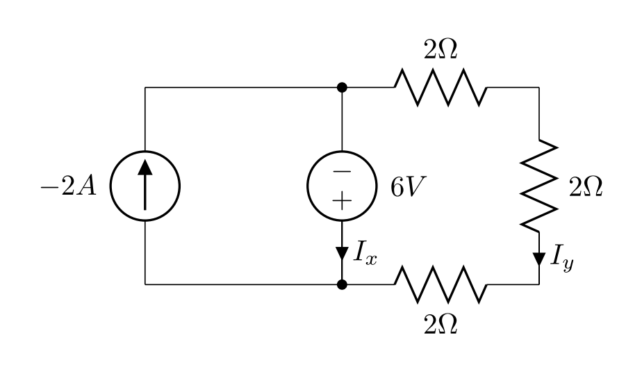
Find  and
and  :
:
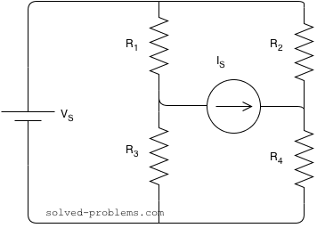
What’s up? We are going to have fun!
This is our first contest for electrical circuits. Solve the problem, submit your answers and cross your fingers to be the lucky winner!
Find and :

Find using superposition rule: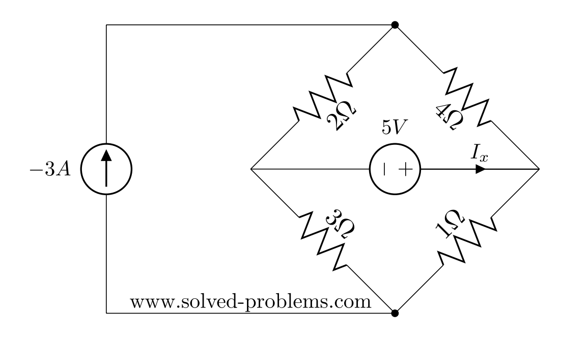
The superposition theorem states that the response (voltage or current) in any branch of a linear circuit which has more than one independent source equals the algebraic sum of the responses caused by each independent source acting alone, while all other independent sources are turned off (made zero).
(more…)
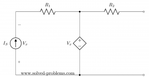
Find Thevenin’s and Norton’s Equivalent Circuits:
Suppose that  ,
,  and
and  .
.
The circuit has both independent and dependent sources. In these cases, we need to find open circuit voltage and short circuit current to determine Norton’s (and also Thevenin’s) equivalent circuits.
(more…)

Find current of resistors, use the current division rule.
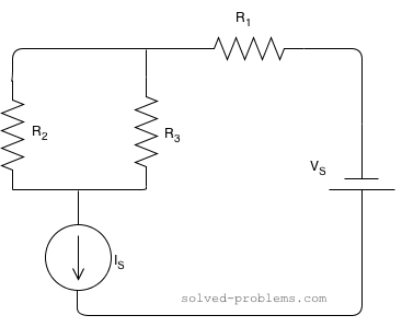
Suppose that  ,
,  ,
,  ,
,  and
and 
Solution:
 and
and  are parallel. The current of
  is passing through them and it is actually divided between them. The branch with lower resistance has higher current because electrons can pass through that easier than the other branch. Using the current division rule, we get
(more…)
Solve the circuit and find the power of sources:
 ,
,  , ,
, ,  , ,
, ,  .
.
Solution:
There are three meshes in the circuit. So, we need to assign three mesh currents. It is better to have all the mesh currents loop in the same direction (usually clockwise) to prevent errors when writing out the equations.
(more…)
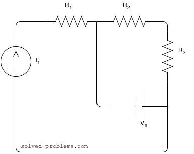
Find the voltage across the current source and the current passing through the voltage source.
Assume that  , ,
, ,  ,
,  ,,
,,  ,
,
Solution
 is in series with the current source; therefore, the same current passing through it as the current source:
(more…)
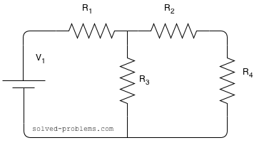
Determine voltage across and  using voltage division rule.
Assume that
 ,
,  ,
,  ,
,  and
and 
Solution:
Please note that the voltage division rule cannot be directly applied. This is to say that:
(more…)
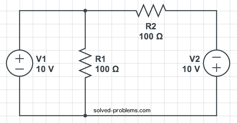
Find resistor currents using KVL.
Solution:
and  are parallel. So the voltage across is equal to . This can be also calculated using KVL in the left hand side loop:
Find the total energy stored in the circuit.

Solution
The circuit contains only dc sources. Recall that an inductor is a short circuit to dc and a capacitor is an open circuit to dc. These can be easily verified from their current-voltage characteristics. For an inductor, we have  . Since a dc current does not vary with time,
  . Hence, the voltage across the inductor is zero for any dc current. This is to say that dc current passes through the inductor without any voltage drop, exactly similar to a short circuit. For a capacitor, the current-voltage terminal characteristics is
  . Voltage drop across passive elements due to dc currents does not vary with time. Therefore,
  and consequently the current of the capacitor is zero. This is to say that dc current does not pass through the capacitor regardless of the voltage amount. This is similar to the behavior of an open circuit. Please note that unlike dc current, ac current passes through capacitors in general.
(more…)
Use Thévenin’s theorem to determine  .
.

Solution
Lets break the circuit at the  load as shown in Fig. (1-27-2).
(more…)