In AC circuit analysis, if the circuit has sources operating at different frequencies, Superposition theorem can be used to solve the circuit. Please note that AC circuits are linear and that is why Superposition theorem is valid to solve them.
Problem
Determine  where
where  and
and  .
.
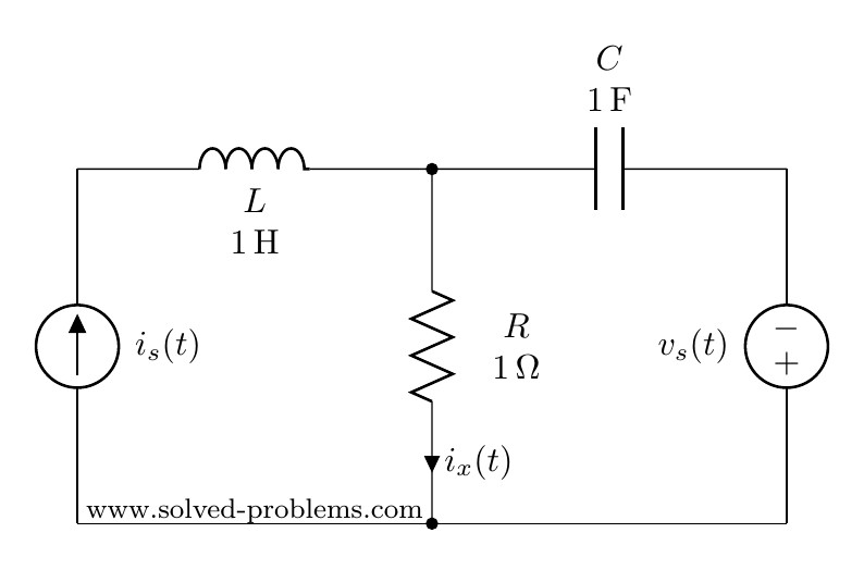
Solution with AC Circuit Analysis
Since sources are operating at different frequencies, i.e.  and
and  , we have to use the Superposition theorem. That is to say that we need to determine contribution of each source on . Then, the final answer is to obtained by adding the individual responses in the time domain. Please note that, since the impedances depend on frequency, we need to have a different frequency-domain circuit for each frequency.
Contribution of the current source
To find the contribution of the current source, we need to turn off other source(s). So, we need to turn off the voltage source. This is very similar to DC circuits that we discussed before:
Voltage sources become a short circuit when turned off.
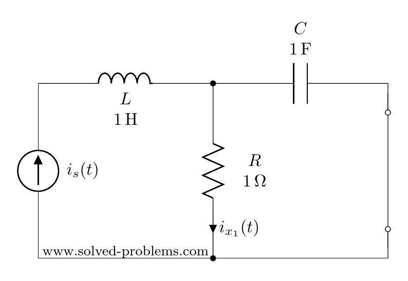
Frequency domain
We first convert the circuit to the frequency domain:


Using current divider:


Time domain
Conversion to time-domain:

Please note that the sinusoidal function for  is cosine and consequently, cosine must be used in converting
  to the time domain.
Contribution of the voltage source
To find the contribution of the voltage source, the current source needs to be turned off. As mentioned before:
To turn off a current source it should be replaced by an open circuit
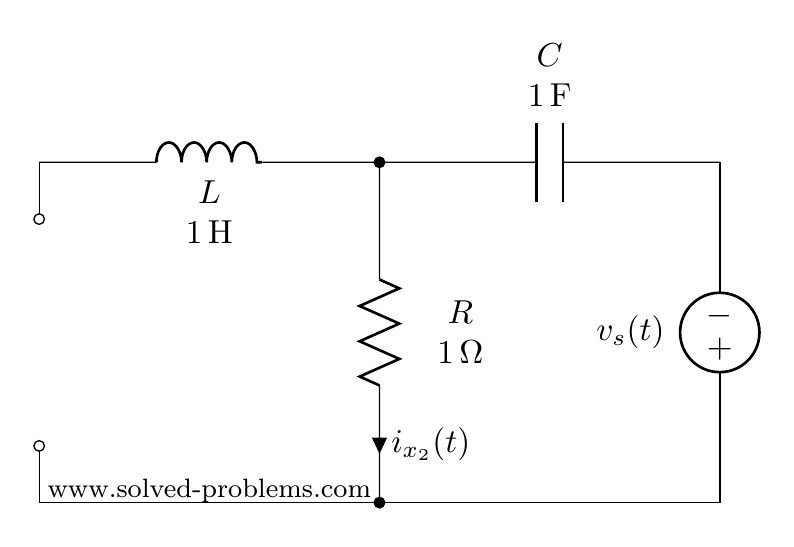
Frequency domain


As the inductor branch is open, this is a very simple circuit with three elements in series:  ,
,  and
and  . Therefore,


Time domain

(why  ?)
?)
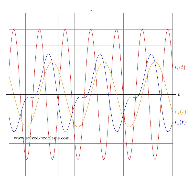
Answer
Now that we have determined both  and
and  in time domain, we can go ahead and add them up to find . Please note that we could not add and
  because they are not phasors with the same frequency.

 and the voltage across
  .
.