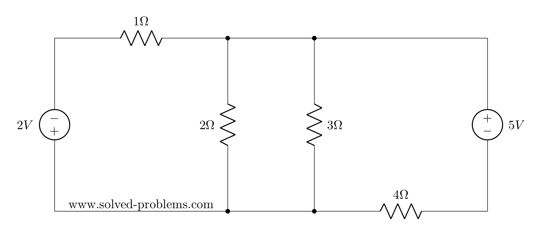
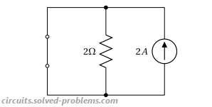
Find the current passing through the 2Ω resistor using superposition.

In AC circuit analysis, if the circuit has sources operating at different frequencies, Superposition theorem can be used to solve the circuit. Please note that AC circuits are linear and that is why Superposition theorem is valid to solve them.
Determine  where
where  and
and  .
.
Since sources are operating at different frequencies, i.e.  and
and  , we have to use the Superposition theorem. That is to say that we need to determine contribution of each source on . Then, the final answer is to obtained by adding the individual responses in the time domain. Please note that, since the impedances depend on frequency, we need to have a different frequency-domain circuit for each frequency.
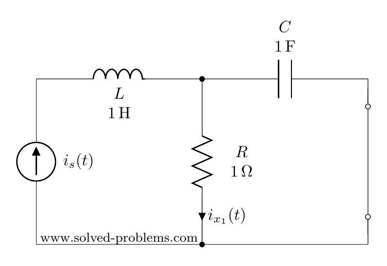
To find the contribution of the current source, we need to turn off other source(s). So, we need to turn off the voltage source. This is very similar to DC circuits that we discussed before:
Voltage sources become a short circuit when turned off.
We first convert the circuit to the frequency domain:


Using current divider:


Conversion to time-domain:

Please note that the sinusoidal function for  is cosine and consequently, cosine must be used in converting
  to the time domain.
To find the contribution of the voltage source, the current source needs to be turned off. As mentioned before:
To turn off a current source it should be replaced by an open circuit
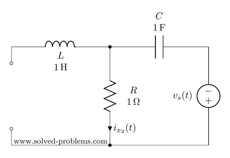


As the inductor branch is open, this is a very simple circuit with three elements in series:  ,
,  and
and  . Therefore,


(why  ?)
?)
Now that we have determined both  and
and  in time domain, we can go ahead and add them up to find . Please note that we could not add and
  because they are not phasors with the same frequency.


Find  using superposition rule:
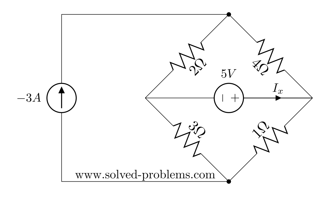
The superposition theorem states that the response (voltage or current) in any branch of a linear circuit which has more than one independent source equals the algebraic sum of the responses caused by each independent source acting alone, while all other independent sources are turned off (made zero).
(more…)

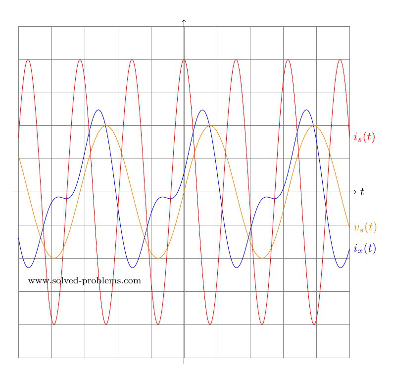
Determine  ,
,  and
and  using the superposition method.

Solution
I. Contribution of the  voltage source:
We need to turn off the current source by replacing it with an open circuit. Recall that we do not turn off dependent sources. The resulting circuit is shown below.
(more…)
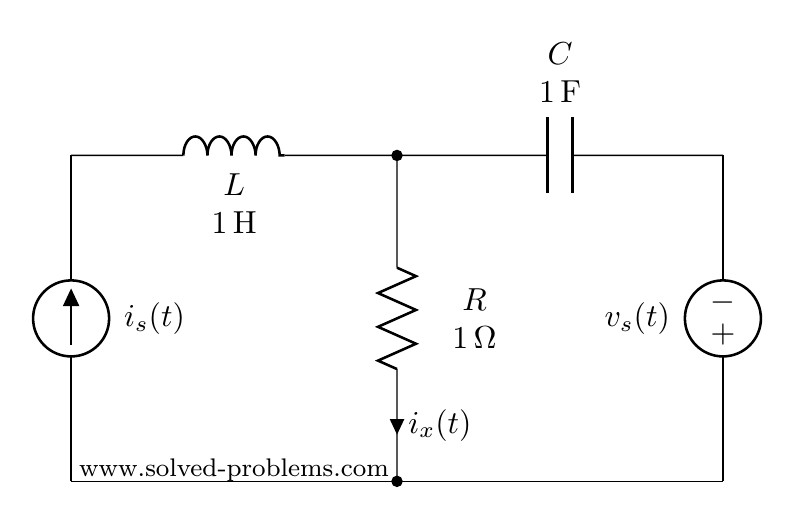
Determine  and
and  using the superposition method.

Solution
I. Contribution of the  voltage source:
To find the contribution of the voltage source, other three sources should be turned off. The  voltage source should be replaced by short circuit. The current source should be replaced with open circuits, as shown below.
(more…)
Turning off a source, which is usually used in solving circuits with superposition method, means setting its value equal to zero. For a voltage source, setting the voltage equal to zero means that it produces zero voltage between its terminals. Therefore, the voltage source must insure that the voltage across two terminals is zero. Replacing the source with a short circuit can do that. Thus, voltage sources become a short circuit when turned off.
For a current source, setting the current equal to zero means that it produces zero current. Therefore, the current source must insure that no current flows through its branch. An open circuit can do that. Hence, to turn off a current source it should be replaced by an open circuit.
How about dependent sources? The voltage/current of a dependent source is dependent on other variables of the circuit. Therefore, dependent sources cannot be turned off.
Example I: Turn off sources one by one.

Solution:
I) The voltage source: