Superposition Method – Circuit With Dependent Sources

Determine  I_x ,  I_y and  V_z using the superposition method.

Superposition - Circuit with dependent sources

Solution
I. Contribution of the  -2V voltage source:
We need to turn off the current source by replacing it with an open circuit. Recall that we do not turn off dependent sources. The resulting circuit is shown below.

Superposition - Circuit with dependent sources - Contribution of the -2V  voltage source
In the left hand side loop, we have
 6I_{x1}=1 \Omega \times I_{y1}

and in the right hand loop, it is trivial that
 2I_{y1}=I_{x1} .
Therefore,  I_{x1}=I_{y1}=0 . Applying KVL around the inner loop,
 -V_{z1}-1\Omega\times I_{y1}+(-2V)-2\Omega \times I_{x1}=0
Substituting  I_{x1}=I_{y1}=0 , we have
 V_{z1}=-2V .

II. Contribution of the  11A current source:
The independent voltage source must be replaced with a short circuit as shown below.
Superposition - Circuit with dependent sources - Contribution of the 11A current source
The  1\Omega resistor is parallel with the dependent voltage source, Therefore,  V_{1\Omega}=6I_{x2} and since  V_{1\Omega}=1\Omega \times I_{y2} , we have  6I_{x2}=I_{y2} . Applying KCL at the right bottom node,  11A-I_{x2}+2I_{y2} . So,

 \left\{ \begin{array}{l} 6I_{x2}=I_{y2} \\ I_{x2}-2I_{y2}=11 \end{array} \right. \to \left\{ \begin{array}{l} I_{x2}=-1 A \\ I_{y2}=-6A \end{array} \right.
Applying KVL around the inner loop,
 +2\Omega \times I_{x2}+1 \Omega \times I_{y2}+V_{z2}=0 \to V_{z2}=8V.

III. The final result

 I_x=I_{x1}+I_{x2}=-1 A
 I_y=I_{y1}+I_{y2}=-6 A
 V_z=V_{z1}+V_{z2}=6V

Comments

13 responses to “Superposition Method – Circuit With Dependent Sources”

  1. Sophie Kovalevsky Avatar
    Sophie Kovalevsky

    I have other solution to solve the problem.

    I used mesh analysis and others tools. I’ll explain how to get the results.

    We have tres values: I_{1}, I_{2}, I_{3}

    See the image here:
    http://circuits.solved-problems.com/files/2011/01/circuits2.jpg
    It’s not necessary resolve three equations by the mesh cause we know two of them.

    I_{3} = 2I_{y}
    I_{2} = -11

    We only need do our mesh 1 equation:

    6I_{x} -I_{1} + I_{2}= 0

    I puted two nodes on the circuits to have more information about the currents that we have.

    Node A
    I_{2}  + I_{x} -I_{3} = 0

    Node B

    I_{1}-I_{y}-I_{2} = 0

    We have then:

    \left.\begin{array}{rcl} 6I_{x} - I_{1} & = & 11\\ I_{x} - 2I_{y} & =  & 11\\ I_{1} - I_{y} & =  & -11 \end{array} \right\}

    We could be more exactly in our equations to find Ix and I1

    \left. \begin{array}{rcl} I_{x} -2I_{1} & = & 33 \\6I_{x} -I_{1} &  = & 11 \end{array} \right\}

    Solving that:

    I_{x} = -1 A \\I_{1} = -17 A

    In this way, with one of our equation we could fin the other value:

    I_{y} = - 6 A

    To find the V_z, we could do a simple KVL across the mesh 2.

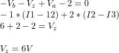
    -V_{b} - V_{z} + V_{a} - 2 = 0 \\ -1*(I1-12) + 2*(I2-I3) \\6 +2 - 2 = V_{z} \\ \\V_{z} = 6 V

  2. Sophie Kovalevsky Avatar
    Sophie Kovalevsky

    I don’t know what’s happen with the latex code above the post. :S

    I’m sure that all the code is able to show it.

    In other way, I tried to show the image wioth html code too, but the system don’t show the image.

    I’ll write here the link of the circuit draw:

    http://s1225.photobucket.com/albums/ee383/sophiekovalevsky/?action=view&current=circuits2.jpg

  3. sunil kumar Avatar
    sunil kumar

    i didn’t get anything .
    in first loop how currents are xero.
    and yes what is vx in that
    from where it comes from and what it representing

    1. sagar Avatar
      sagar

      hey sunil vx1 is nothing but vz1
      finally in Vz=Vz1+Vz2
      he uses Vx1 as Vz1

      1. Dr. Yaz Z. Li Avatar

        Thank you for your reply. I made corrections in the text.

        1. nitishbhardwaj2 Avatar
          nitishbhardwaj2

          what to do with thevenins eqivalent with 1dependent &1 independent source

  4. fawad humayun Avatar
    fawad humayun

    Sir this question is quite difficult i donot understand this question
    Sir please give me some tips about these type of question
    Thanks

  5. mitch mccown Avatar
    mitch mccown

    The resistances of commercially-available discrete resistors are restricted to particular sets. For example, the available values of resistors with 10% tolerance are selections from the E12 set multiplied by a power of ten from 10^0 through 10^5. The E12 set is
    E12={10, 12, 15, 18, 22, 27, 33, 39, 47, 56, 68, 82}
    Thus, you can buy 10% resistors with a nominal resistance of 330Ω or 33kΩ, but not 350Ω.
    The “tolerance” means that if you buy a 10% 390Ω resistor you can be sure that its resistance is between 351Ω and 429Ω.
    In this problem we need to choose 10% resistors to make a voltage divider that meets a given specification.

    We are given an input voltage Vin=30.0V, and we need to provide an open-circuit output voltage of Vout≈10.5V. An additional requirement is that the Thevenin resistance as seen from the output terminals is between 10kΩ and 30kΩ. Assume first that the resistors have their nominal resistance. Come up with resistors R1 and R2 such that the division ratio Vout/Vin is within 10% of the requirement.
    Of course, the resistances you chose are just nominal. Given that they are only guaranteed to have resistances within 10% of the nominal value, what is the largest and smallest value that Vout may have?
    Enter your values here.

    R1 (in Ohms):
    R2 (in Ohms):

    Vmax (in Volts):
    Vmin (in Volts):

    H2P2: SOLAR POWER

    A simple model of a photovoltaic solar cell is a current source, with the current proportional to the amount of sunlight falling on it. A more accurate model includes a diode (a nonlinear element we will see later). There is some leakage current that we can model with a parallel resistor, and there is a voltage drop in the interconnect that we can model with series resistances connecting to the load resistor. So a crude model of a complete system might be the circuit shown below.

    In this system we have I=0.7A, Rp=0.857142857143Ω, and Rs=1.1Ω.
    You are to determine the load resistance, RL, for which the maximum power is transferred to the load. (Hint: remember your calculus!)
    What is this optimum load resistance (in Ohms)?

    What is the power (in Watts) that is delivered to this best load resistance?

    What is the Thevenin equivalent resistance (in Ohms) of the power source as seen by the load resistance?

    Hmmmmmm.

    H2P3: LOGIC DIAGRAMS

    In the figure above there are four two-input two-output logic circuits. Each circuit is equivalent, in that it computes the same logic function, as another circuit in the figure.
    Which circuit is equivalent to circuit number 3? Enter the number of the equivalent circuit in the box provided:

    The truth table for a two-input function has only four lines.

    Fill in the missing information in the truth table for the circuit number 3.
    What is the entry in the box labeled a?

    What is the entry in the box labeled b?

    What is the entry in the box labeled c?

    What is the entry in the box labeled d?

    What is the entry in the box labeled e?

    What is the entry in the box labeled f?

    What is the entry in the box labeled g?

    What is the entry in the box labeled h?

  6. Anonymous Avatar
    Anonymous

    plz reply the answer of the above question

  7. R Avatar
    R

    Does it mean contribution by dependent sources is ZERO?

  8. CHEMIATI ANTHONY Avatar
    CHEMIATI ANTHONY

    Fantastic

  9. Shweta Avatar
    Shweta

    Plz give 8 source example of supperposition theorem

Leave a Reply

Your email address will not be published. Required fields are marked *