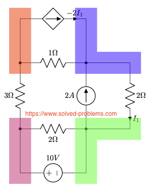
Deploy nodal analysis method to solve the circuit and find the power of the dependent source.

I. Identify all nodes in the circuit.
The circuit has 4 nodes.
II. Select a reference node. Label this node with the reference (ground) symbol.
All nodes have the same number of elements. We prefer to select one of the nodes connected to the voltage source to avoid having to use a super-node.
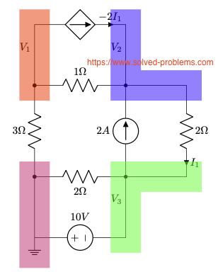
III. Assign variables for unknown node voltages.
We label the remaining three nodes as shown above.
IV. Incorporate dependent sources.
If there are dependent sources in the circuit, write down equations that express their values in terms of node voltages.
There is one dependent source, which is a current controlled current source. We need to write  in terms of node voltages.
  is the current passing through the
  – resistor. Applying the Ohm’s law,
![\[I_1 = \frac{V_2-V_3}{2\Omega}\]](https://www.solved-problems.com/wp-content/ql-cache/quicklatex.com-c565ca9ebd3ad90607f355f401318006_l3.png "Rendered by QuickLaTeX.com")
Hence,
![\[-2I_1 = V_3-V_2\]](https://www.solved-problems.com/wp-content/ql-cache/quicklatex.com-e9e353abf8e62d02e607459cebc91278_l3.png "Rendered by QuickLaTeX.com")
V. Apply Kirchhoff’s Current Law (KCL).
Node  :
:
![\[\frac{V_1}{3 \Omega}+\frac{V_1-V_2}{1\Omega}-2I_1=0\]](https://www.solved-problems.com/wp-content/ql-cache/quicklatex.com-c427776401937bf2baf695797e56b49b_l3.png "Rendered by QuickLaTeX.com")
(1) ![\[to 4V_1-6V_2+3V_3=0 \]](https://www.solved-problems.com/wp-content/ql-cache/quicklatex.com-1040319bf773805ea96213bc81b24883_l3.png "Rendered by QuickLaTeX.com")
Node  :
:
![\[2I_1+\frac{V_2-V_1}{1\Omega}-2A+\frac{V_2-V_3}{2\Omega}=0\]](https://www.solved-problems.com/wp-content/ql-cache/quicklatex.com-194e5586ca21ae014f485163b2986b3e_l3.png "Rendered by QuickLaTeX.com")
Please note that we avoid using all unknowns except node voltages. Using in this KCL equation introduces an unnecessary unknown to the equations set. Substituting  and rearranging results in:
(2) ![\[-2V_1+5V_2-3V_3=4 \]](https://www.solved-problems.com/wp-content/ql-cache/quicklatex.com-1bf8ef03443f0e5951bc96b6578f7c95_l3.png "Rendered by QuickLaTeX.com")
Node  has a voltage source connected to. Therefore,
  .
.
Substituting this in Eq. 1 and Eq.2 leads to
![\[\left{\begin{array}{l} 4V_1-6V_2=-30 \ -2V_1+5V_2=34 \end{array}\right.\]](https://www.solved-problems.com/wp-content/ql-cache/quicklatex.com-7f26b6e02313e6bc7371fbacc56d1da8_l3.png "Rendered by QuickLaTeX.com")
VI. Handle super-nodes.
There is no super-node in this circuit.
VII. Solve the System of Equations.
By solving the system of equations, and
and  .
.
VIII. Determine Additional Variables.
Now, we need to find the voltage across the dependent current source and the current passing through it. Lets start with . .
.
Assuming positive terminal placed on the node of , the voltage across the dependent current source is  . The current flowing through the dependent current source is
  . Therefore the power of the dependent current source is
  . Because the current direction and the voltage polarity is in accordance with the passive sign convention and the power is negative, the dependent current source is supplying power.
Download the Circuit File
To download the LTspice circuit file for your own simulations, click the link below.Please remember to unzip the file after downloading to access the .asc file for your simulations:

Leave a Reply