Solved problems in resistive circuits such as nodal analysis, mesh analysis, superposition, source transformation, Thevenin and Norton theorems and so on
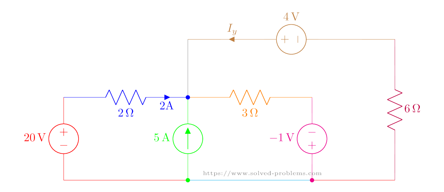
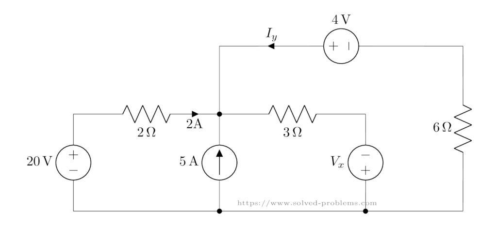
Use Kirchhoff’s Voltage Law (KVL) and Kirchhoff’s Current Law (KCL) to find and .
Applying Kirchhoff’s Voltage Law (KVL)
KVL states: The sum of all voltages in a closed loop is zero.
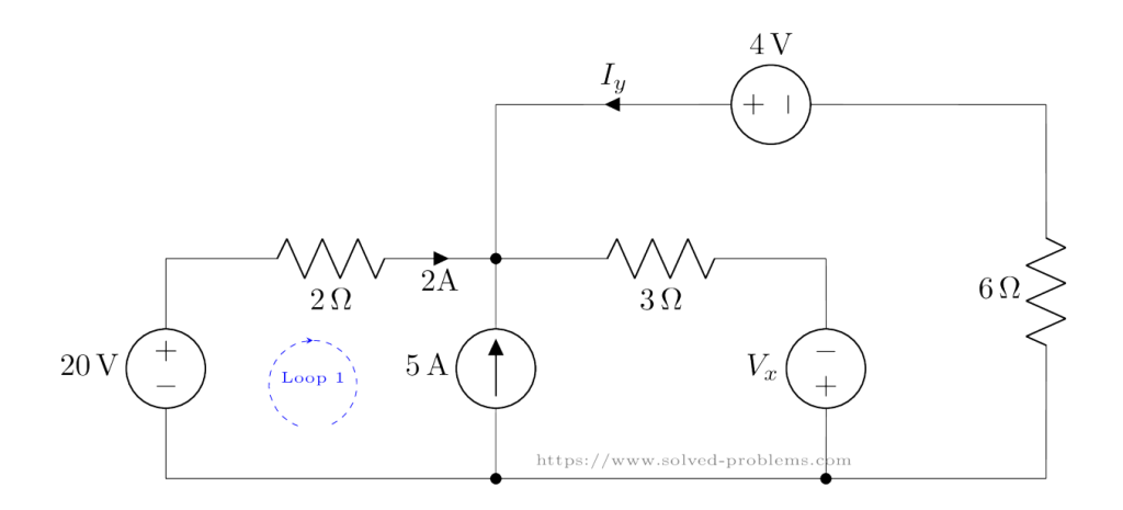
Loop 1: 20V Source, 2Ω Resistor, and 5A Current Source
We start with Loop 1 which is shown below.
The KVL equation is:
Simplify:
Loop 2: Voltage Across, 3V Source, and 7Ω Resistor
Next, we analyze Loop 2 shown below:
The equation is:
Simplify:
KCL: Applying Kirchhoff’s Current Law (KCL)
KCL states: The total current entering a node equals the total current leaving the node.
At the middle node, the currents are:
Simplify:
Finding
Finally, we calculate using KVL in Loop 3:
The equation is:
Simplify:
Using Python to Solve the Circuit
One powerful way to solve electrical circuits is by using the Lcapy library in Python. Lcapy is an open-source Python package designed for symbolic linear circuit analysis and signal processing.
Below is an example of how to use Lcapy to solve the given circuit and find (the current through ) and (the current through the 2Ω resistor).
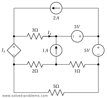
Determine the power of each source after solving the circuit by the nodal analysis.
Answers: and
Solution
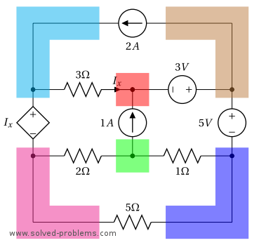
I. Identify all nodes in the circuit. The circuit has 6 nodes as highlighted below.
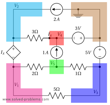
II. Select a reference node. Label this node with the reference (ground) symbol.
The right top node is connected to two voltage sources and has three elements. All other nodes also have three elements. Hence, we select the right top node because by this selection, we already know the node voltages of two other nodes, i.e. the ones that the reference node is connected to them by voltage sources.
III. Assign variables for unknown node voltages. We label the remaining nodes as shown above. Nodes of and are connected to the reference node through voltage sources. Therefore, and can be found easily by the voltages of the voltage sources. For , the negative terminal of the voltage source is connected to the node. Thus, is equal to minus the source voltage, . The same argument applies to and .
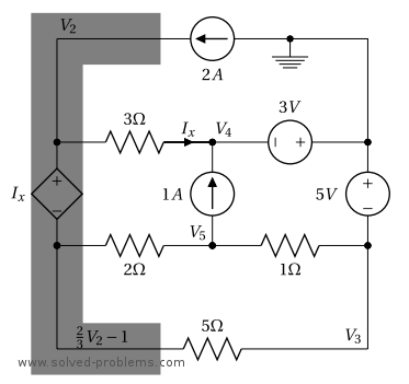
IV. Incorporate dependent sources. If there are dependent sources in the circuit, write down equations that express their values in terms of node voltages.
The voltage of the dependent voltage source is . We should find this value in terms of the node voltages. is the current of the – resistor. The voltage across the resistor is . We prefer to define as instead of to comply with passive sign convention. By defining as mentioned, is entering from the positive terminal of and we have . Therefore, .
V. Apply Kirchhoff’s Current Law (KCL) / VI. Handle super-nodes. Nodes of and : These two nodes are connected through a voltage source. Therefore, they form a supernode and we can write the voltage of one in terms of the voltage of the other one. Please note that the voltage of the dependent voltage source is and we have
KCL for the supernode: Substituting ,
Node of : Substituting and ,
Here is the system of equations that we need to solve and obtain nd :
VII. Solve the System of Equations.
We use elimination method to solve this system of equation: Using ,
VIII. Determine Additional Variables.
All node voltages are determined. Now, the power of voltage sources can be calculated from the node voltages. For each source, we need to find the voltage across the source as well as the current flowing through it to compute the power.
current source: The voltage across the current source is equal to . However, the comply with the passive voltage convention, the current should be entering from the positive terminal of the defined voltage as shown below. Therefore, .
absorbing power
current source:
To compliant with the passive sign convention, the voltage should be defined with polarity as indicated above. We have . Hence,
supplying power.
voltage source:
should be defined such that it enters from the positive terminal of the source in order to use the voltage of the source in power calculation. Another option is to use and define the current as entering from the voltage source terminal connected to the node of . We use the first approach here. KCL should be applied in the node of to determine .
KCL @ Node of :
supplying power.
voltage source:
Likewise, should be defined as shown above to comply with the passive sign convention. We apply KCL to the reference node to find .
KCL @ the reference node:
supplying power.
The dependent source: The voltage of the dependent source is and we define its current with the direction illustrated above. can be calculated by applying KCL at the node of . The current of the resistor is which is equal to .
KCL @ Node of :
absorbing power.
Download the Circuit File
To download the LTspice circuit file for your own simulations, click the link below.Please remember to unzip the file after downloading to access the .asc file for your simulations:
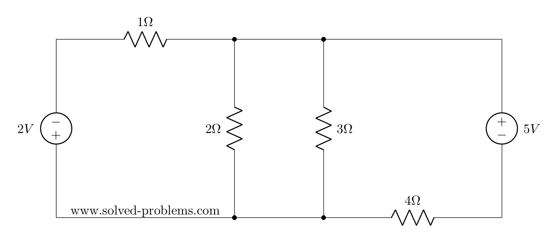
Determine the power of each source after solving the circuit by the nodal analysis.
I. Identify all nodes in the circuit.
The circuit has 6 nodes as indicated below:
II. Select a reference node. Label this node with the reference (ground) symbol.
The bottom left node is connected to 4 nodes while the other ones are connected to three or less elements. Therefore, we select it as the reference node of the circuit.
III. Assign variables for unknown node voltages.
We label the remaining nodes as shown above. is connected to the reference node through a voltage source. Therefore, it is equal to the voltage of the voltage source: .
IV. Incorporate dependent sources. There are no dependent sources in this circuit.
V. Apply Kirchhoff’s Current Law (KCL) / VI. Handle super-nodes.
Nodes of and are connected by a voltage source. Therefore, they form a super-node. The negative terminal of the voltage source is connected to and the positive terminal is connected to . Thus,
This can also be verified by a KVL around the loop which starts from the reference node, jumps to the node of with (the reference is always assumed to be the negative terminal of node voltages), passes through the voltage source by and returns back to the reference node from as
Super-node of & :
Node of :
Node of :
Hence, we have the following system of equations:
VII. Solve the System of Equations.
This system of equations can be solved by any preferred method such as elimination, row reduction, Cramer’s rule or other methods. We use the Cramer’s rule here:
VIII. Determine Additional Variables.
After solving for all node voltages, we can calculate the currents and powers for the sources in the circuit as follows:
Current of the Source:
The current through the source is the same as the current through the resistor. Using Ohm’s Law, this current is:
The current direction is chosen such that it enters the positive terminal of the voltage source, in compliance with the \textit{passive sign convention}.
The power delivered by the source is then:
Since the power is negative, the source is \textbf{absorbing power}.
Current of the Source:
The current through the source is the sum of the currents through the and resistors. Using Ohm’s Law, we calculate:
Substituting the values:
The power delivered by the source is:
Since the power is positive, the source is supplying power.
Voltage Across the Current Source:
The voltage across the current source is given by the difference in node voltages:
The power delivered by the source is:
Since the power is negative, the source is \textbf{supplying power}.
Download the Circuit File
To download the LTspice circuit file for your own simulations, click the link below.Please remember to unzip the file after downloading to access the .asc file for your simulations:
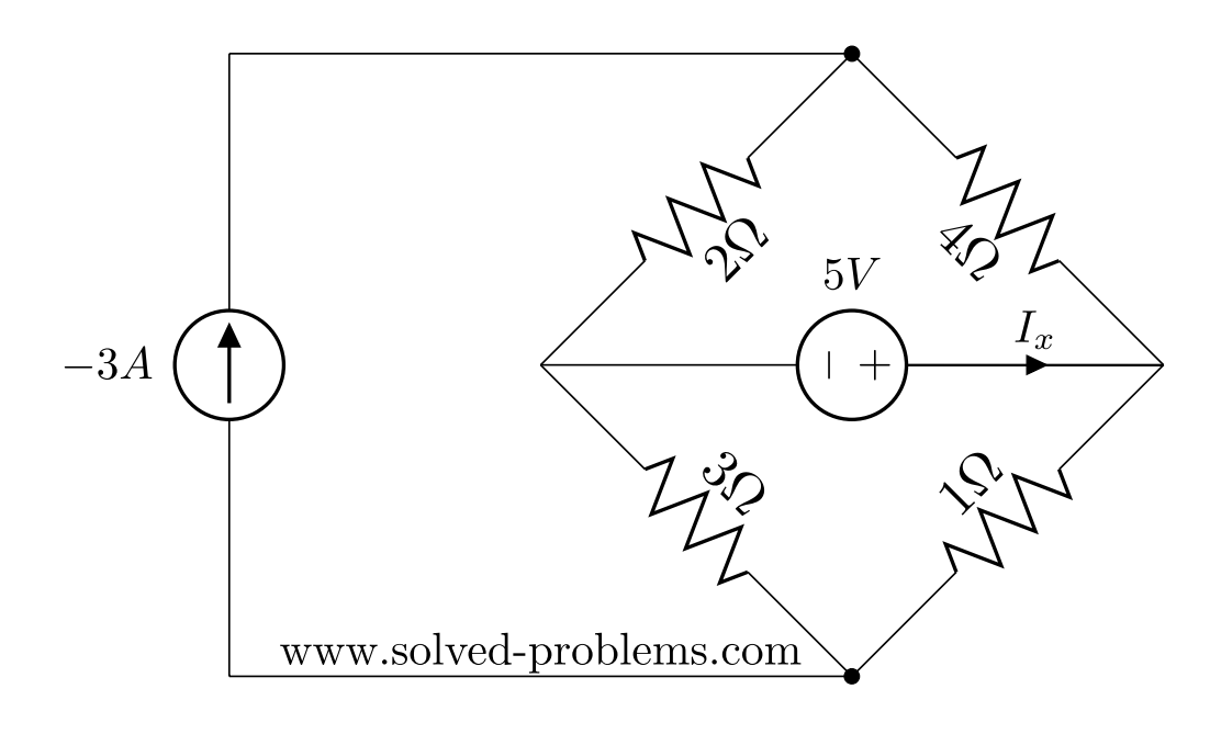
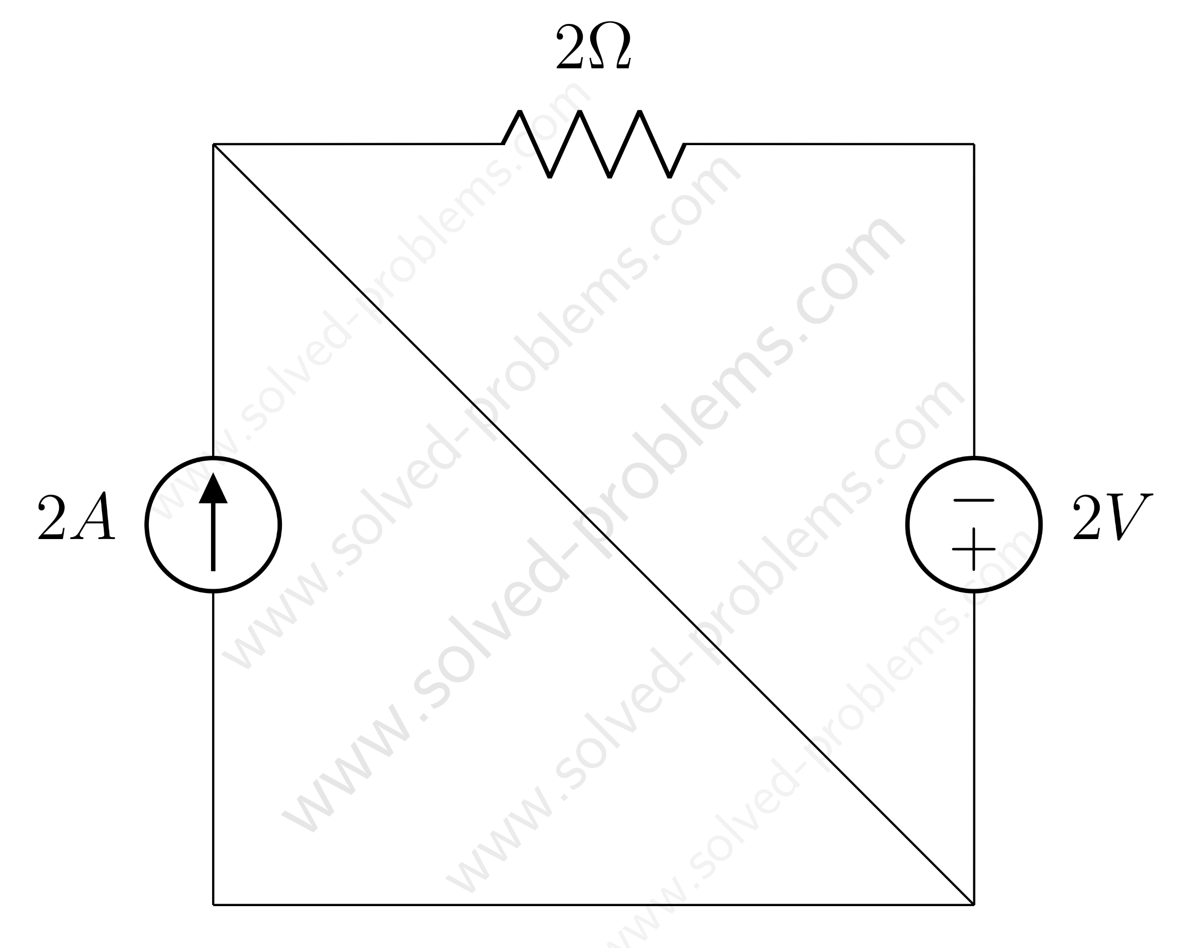
Solve the circuit by mesh analysis and find the current and the voltage across .
Solution
Mesh Analysis
There are four meshes in the circuit. So, we need to assign four mesh currents. It is better to have all the mesh currents loop in the same direction (usually clockwise) to prevent errors when writing out the equations. (more…)
The superposition theorem states that the response (voltage or current) in any branch of a linear circuit which has more than one independent source equals the algebraic sum of the responses caused by each independent source acting alone, while all other independent sources are turned off (made zero). (more…)
 and
and  .
.
![\[-20V - (2\Omega \cdot 2A) + V_{5A} = 0\]](https://www.solved-problems.com/wp-content/ql-cache/quicklatex.com-64caed8ac69b7484d9948a6784a93c2a_l3.png "Rendered by QuickLaTeX.com")
![\[-20V - 4V + V_{5A} = 0\]](https://www.solved-problems.com/wp-content/ql-cache/quicklatex.com-66b411bdf4162cc5c5c7cd38867f2607_l3.png "Rendered by QuickLaTeX.com")
![\[V_{5A} = 16V\]](https://www.solved-problems.com/wp-content/ql-cache/quicklatex.com-48a119a380d9efbe938a422a88c109d6_l3.png "Rendered by QuickLaTeX.com")
 , 3V Source, and 7Ω Resistor
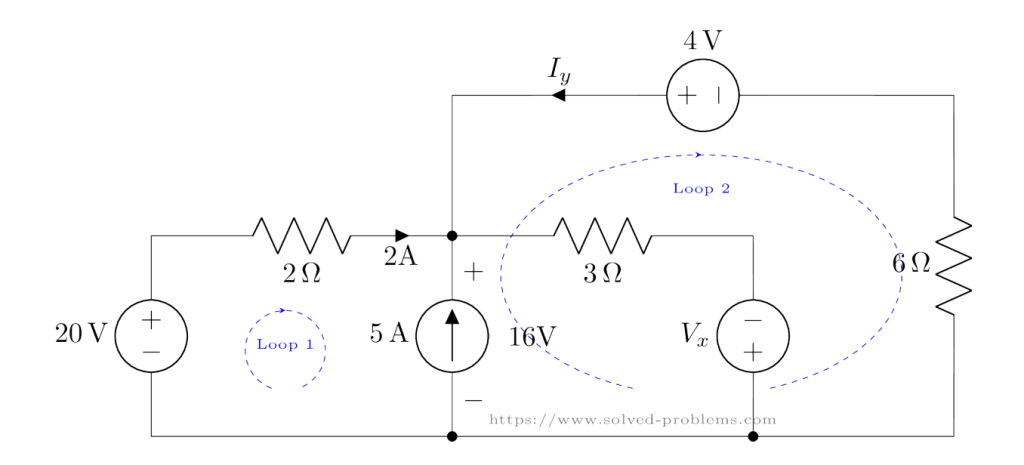
![\[-16V + 4V - (6\Omega \cdot I_y) = 0\]](https://www.solved-problems.com/wp-content/ql-cache/quicklatex.com-59fdeebf2e0fdd6a65cbd4312bd62bb6_l3.png "Rendered by QuickLaTeX.com")
![\[-12V -6\Omega \cdot I_y = 0\]](https://www.solved-problems.com/wp-content/ql-cache/quicklatex.com-e978cd695ce092e1e2e95d4b7981968b_l3.png "Rendered by QuickLaTeX.com")
![\[I_y = -2A\]](https://www.solved-problems.com/wp-content/ql-cache/quicklatex.com-e305547c4e2d6ab9cf249eede9dc5bf4_l3.png "Rendered by QuickLaTeX.com")
![\[2A + 5A +(-2A) - I_{3\Omega} = 0\]](https://www.solved-problems.com/wp-content/ql-cache/quicklatex.com-d9d27203dd02f42f7fa42f88692a91f4_l3.png "Rendered by QuickLaTeX.com")
![\[I_{3\Omega} = 5A\]](https://www.solved-problems.com/wp-content/ql-cache/quicklatex.com-1aec79cb1b4e73b1753e4f56d7f922d1_l3.png "Rendered by QuickLaTeX.com")
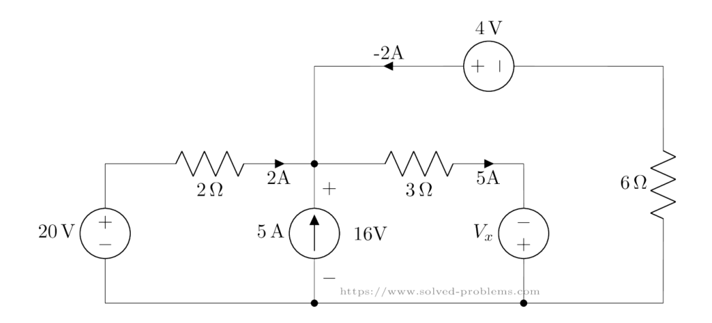
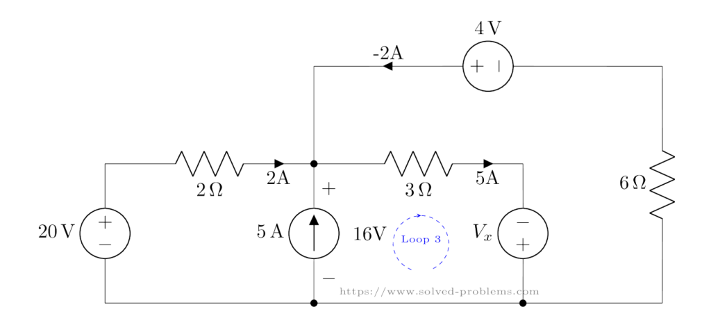
![\[-16V + (3\Omega \cdot 5A) - V_x = 0\]](https://www.solved-problems.com/wp-content/ql-cache/quicklatex.com-ef03c47242ee7580d8fc77146f852d58_l3.png "Rendered by QuickLaTeX.com")
![\[-16V + 15V - V_x = 0\]](https://www.solved-problems.com/wp-content/ql-cache/quicklatex.com-ae909e91cf156fdd5c72792b94199a77_l3.png "Rendered by QuickLaTeX.com")
![\[V_x = -1V\]](https://www.solved-problems.com/wp-content/ql-cache/quicklatex.com-504a0f240397114830c572345ac134a3_l3.png "Rendered by QuickLaTeX.com")
 ) and
) and  (the current through the 2Ω resistor).


 – resistor.
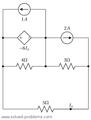

 and
and 
 and
and  are connected to the reference node through voltage sources. Therefore,
  . The same argument applies to
  .
. . We should find this value in terms of the node voltages.
  – resistor. The voltage across the resistor is
  . We prefer to define
  as
as  to comply with passive sign convention. By defining
  . Therefore,
  .
. 
 and
and  :
:


 ,
,
 :
:


 current source:
 .
. absorbing power
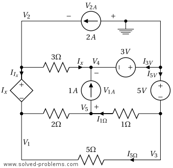
 current source:
 should be defined with polarity as indicated above. We have
  . Hence,
 supplying power.
 voltage source:
 should be defined such that it enters from the positive terminal of the source in order to use the voltage of the source in power calculation. Another option is to use

 supplying power.
 voltage source:
 should be defined as shown above to comply with the passive sign convention. We apply KCL to the reference node to find

 supplying power.
 with the direction illustrated above.
  .
.
 absorbing power.


 is connected to the reference node through a voltage source. Therefore, it is equal to the voltage of the voltage source:
  .
. are connected by a voltage source. Therefore, they form a super-node. The negative terminal of the voltage source is connected to
 ![\[V_2=V_3+2.\]](https://www.solved-problems.com/wp-content/ql-cache/quicklatex.com-34cfc21f3559b4672d9081193ac694eb_l3.png "Rendered by QuickLaTeX.com")
 (the reference is always assumed to be the negative terminal of node voltages), passes through the voltage source by
  and returns back to the reference node from
![\[-V_3-2V+V_2=0 \to V_2=V_3+2.\]](https://www.solved-problems.com/wp-content/ql-cache/quicklatex.com-649ee7a294050e7fff2337ee907b9ff1_l3.png "Rendered by QuickLaTeX.com")
![\[\frac{V_3}{1\Omega}+\frac{V_3-V_4}{5\Omega}+\frac{V_2-V_1}{2\Omega}+\frac{V_2-V_5}{3\Omega}=0\]](https://www.solved-problems.com/wp-content/ql-cache/quicklatex.com-f1e91d3309112c978773d54024fb90cd_l3.png "Rendered by QuickLaTeX.com")
![\[\to {V_3}+\frac{V_3}{5}-\frac{V_4}{5}+\frac{V_3+2-10}{2}+\frac{V_3+2-V_5}{3}=0\]](https://www.solved-problems.com/wp-content/ql-cache/quicklatex.com-5566abcbbd54661d3cf5427f8967b0a9_l3.png "Rendered by QuickLaTeX.com")
![\[\to {V_3}+\frac{V_3}{5}-\frac{V_4}{5}+\frac{V_3}{2}-4+\frac{V_3}{3}+\frac{2}{3}-\frac{V_5}{3}=0\]](https://www.solved-problems.com/wp-content/ql-cache/quicklatex.com-845d693cfddc8403a4e3f4882c29e1d5_l3.png "Rendered by QuickLaTeX.com")
![\[\to \frac{61}{30}V_3-\frac{V_4}{5}-\frac{V_5}{3}=\frac{10}{3}\]](https://www.solved-problems.com/wp-content/ql-cache/quicklatex.com-2e7c80e6818ab31cfe670af42424a3c3_l3.png "Rendered by QuickLaTeX.com")
![\[\to 61 V_3-6 V_4-10 V_5=100\]](https://www.solved-problems.com/wp-content/ql-cache/quicklatex.com-89072ddb695ffe2deb098c693f542b69_l3.png "Rendered by QuickLaTeX.com")
 :
:![\[\frac{V_4}{6\Omega}+\frac{V_4-V_3}{5\Omega}+10=0\]](https://www.solved-problems.com/wp-content/ql-cache/quicklatex.com-568fa5bd8e36e406bd2f86249060293d_l3.png "Rendered by QuickLaTeX.com")
![\[\to 5 V_4+6 V_4-6V_3+300=0\]](https://www.solved-problems.com/wp-content/ql-cache/quicklatex.com-0d7b5dfb55702ea7f0a8eb47e8cc88f1_l3.png "Rendered by QuickLaTeX.com")
![\[\to -6V_3+11 V_4=-300\]](https://www.solved-problems.com/wp-content/ql-cache/quicklatex.com-53f7f294b731212be42c22ddadfdc3c1_l3.png "Rendered by QuickLaTeX.com")
 :
:![\[\frac{V_5}{4\Omega}+\frac{V_5-V_2}{3\Omega}-10=0\]](https://www.solved-problems.com/wp-content/ql-cache/quicklatex.com-774066816a5c0acef1d4335a1c28ca84_l3.png "Rendered by QuickLaTeX.com")
![\[\to 3V_5+4V_5-4V_2-120=0\]](https://www.solved-problems.com/wp-content/ql-cache/quicklatex.com-9b7eacd0118f6ad1ca26dcf10e3972bf_l3.png "Rendered by QuickLaTeX.com")
![\[\to 7V_5-4 V_3-8-120=0\]](https://www.solved-problems.com/wp-content/ql-cache/quicklatex.com-29c998f696da9f88931811251d6e92e9_l3.png "Rendered by QuickLaTeX.com")
![\[\to -4 V_3+7V_5=128\]](https://www.solved-problems.com/wp-content/ql-cache/quicklatex.com-31d31c06b3fa61fac3f2126275f43d48_l3.png "Rendered by QuickLaTeX.com")
![\[\left\{ \begin{array}{l} 61 V_3-6 V_4-10 V_5=100 \\ -6V_3+11 V_4=-300 \\ -4 V_3+7V_5=128 \end{array} \right.\]](https://www.solved-problems.com/wp-content/ql-cache/quicklatex.com-265860250d9eab754e916d35e60577c6_l3.png "Rendered by QuickLaTeX.com")


![Thus, [latex]V_2=V_3+2=4.292.](https://www.solved-problems.com/wp-content/ql-cache/quicklatex.com-29edb764dc83c14df778ad3f3f7f080c_l3.png "Rendered by QuickLaTeX.com")
 Source:
 resistor. Using Ohm’s Law, this current is:
![\[I_{10 \, \mathrm{V}} = \frac{V_2 - V_1}{2 \, \Omega} = -2.854 \, \mathrm{A}.\]](https://www.solved-problems.com/wp-content/ql-cache/quicklatex.com-ffe9ad653492ff77b714d326f3bea820_l3.png "Rendered by QuickLaTeX.com")
![\[P_{10 \, \mathrm{V}} = 10 \times (-2.854) = -28.54 \, \mathrm{W}.\]](https://www.solved-problems.com/wp-content/ql-cache/quicklatex.com-9694d039de3822345ac308ddb7b1dc68_l3.png "Rendered by QuickLaTeX.com")
 Source:
 and
and  resistors. Using Ohm’s Law, we calculate:
![\[I_{2 \, \mathrm{V}} = I_{5 \, \Omega} + I_{1 \, \Omega} = \frac{V_3 - V_4}{5 \, \Omega} + \frac{V_3}{1 \, \Omega}.\]](https://www.solved-problems.com/wp-content/ql-cache/quicklatex.com-9f3093d9504b0c689f1cd276c5f8e3ef_l3.png "Rendered by QuickLaTeX.com")
![\[I_{2 \, \mathrm{V}} = 5.663 + 2.292 = 7.955 \, \mathrm{A}.\]](https://www.solved-problems.com/wp-content/ql-cache/quicklatex.com-9c7e12f483d5f5647ba6e0f48c8e0314_l3.png "Rendered by QuickLaTeX.com")
![\[P_{2 \, \mathrm{V}} = 2 \times 7.955 = 15.91 \, \mathrm{W}.\]](https://www.solved-problems.com/wp-content/ql-cache/quicklatex.com-d7e2a76aeaadf66b99bd8630599a0c70_l3.png "Rendered by QuickLaTeX.com")
 Current Source:
![\[V_{10 \, \mathrm{A}} = V_4 - V_5 = -45.617 \, \mathrm{V}.\]](https://www.solved-problems.com/wp-content/ql-cache/quicklatex.com-2c4d88fa8e030f45ec0505852880de3d_l3.png "Rendered by QuickLaTeX.com")
![\[P_{10 \, \mathrm{A}} = 10 \times (-45.617) = -456.17 \, \mathrm{W}.\]](https://www.solved-problems.com/wp-content/ql-cache/quicklatex.com-e479ec9d7227df7bef098696b8bc745f_l3.png "Rendered by QuickLaTeX.com")


 .
.
 and power absorbed or supplied by each element.
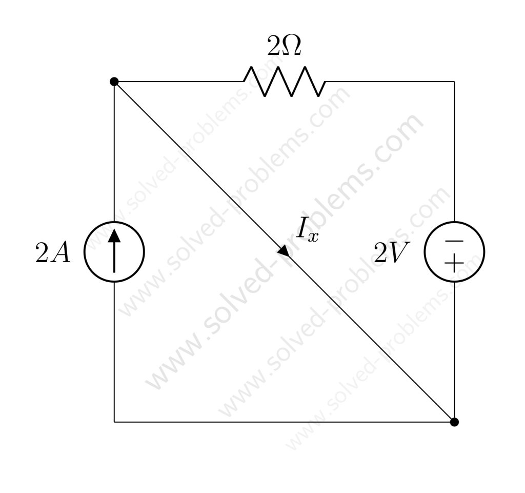

 .
.