Solved the circuit to determine  and power absorbed or supplied by each element.

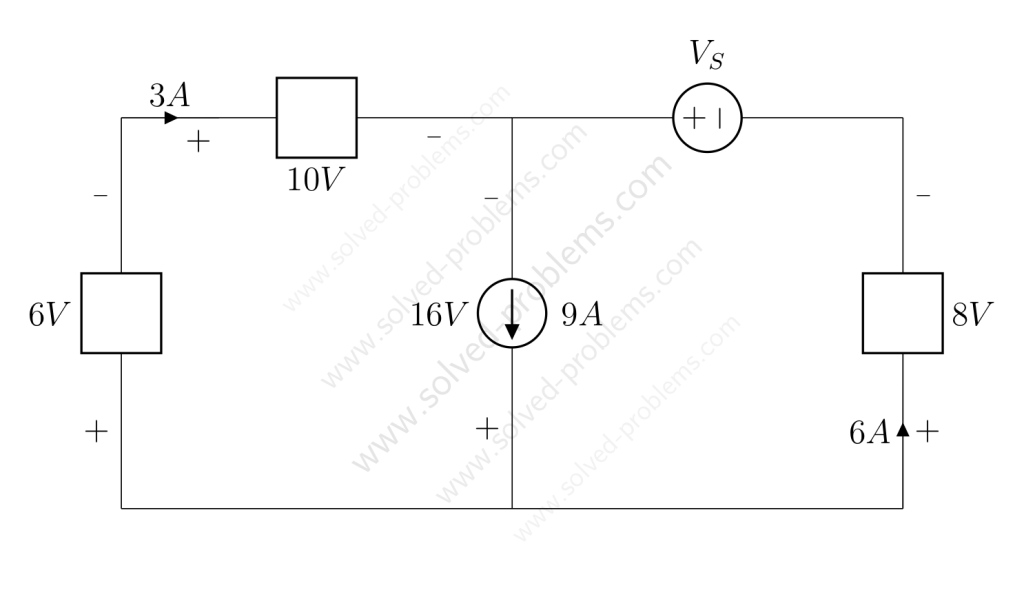
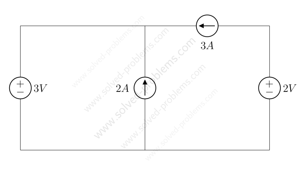
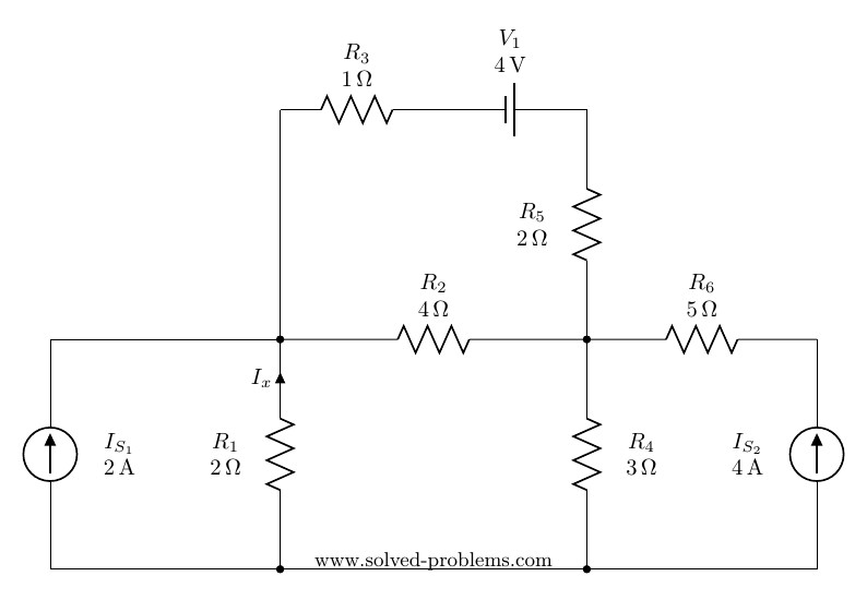
We go through solving a circuit which only containes independent sources: two voltage sources and two current sources. KVL and KCL are used to determine voltages and currents.
Determine the amount of power absorbed or supplied by each source.
I started a YouTube channel where is explain how to solve problems. Check it out: https://www.youtube.com/channel/UCE8fpNEhOoHyf78wGGcgwFg
Here is the first video:
Please let me know what you think!
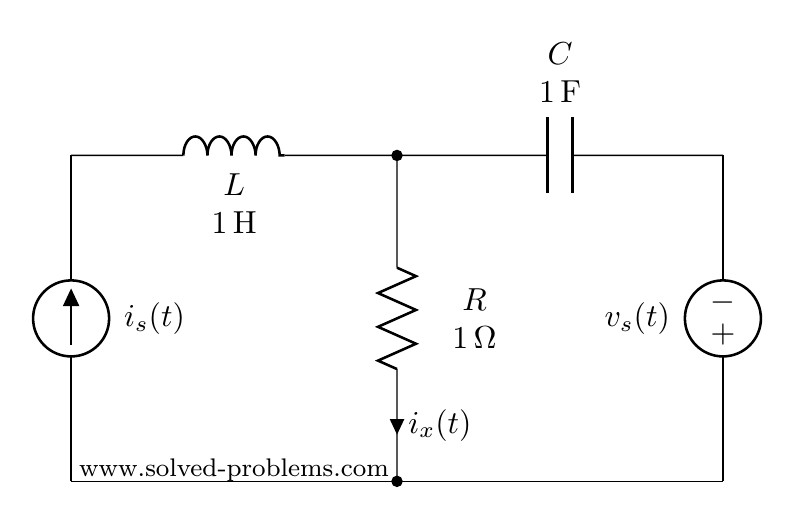
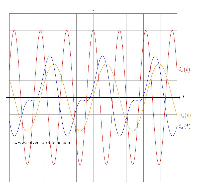
In AC circuit analysis, if the circuit has sources operating at different frequencies, Superposition theorem can be used to solve the circuit. Please note that AC circuits are linear and that is why Superposition theorem is valid to solve them.
Determine  where
where  and
and  .
.
Since sources are operating at different frequencies, i.e.  and
and  , we have to use the Superposition theorem. That is to say that we need to determine contribution of each source on . Then, the final answer is to obtained by adding the individual responses in the time domain. Please note that, since the impedances depend on frequency, we need to have a different frequency-domain circuit for each frequency.
To find the contribution of the current source, we need to turn off other source(s). So, we need to turn off the voltage source. This is very similar to DC circuits that we discussed before:
Voltage sources become a short circuit when turned off.
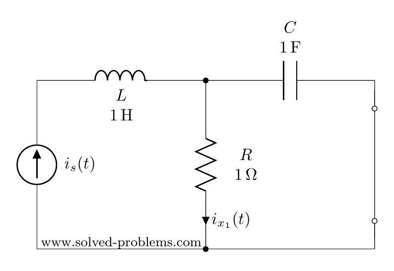
We first convert the circuit to the frequency domain:


Using current divider:


Conversion to time-domain:

Please note that the sinusoidal function for  is cosine and consequently, cosine must be used in converting
  to the time domain.
To find the contribution of the voltage source, the current source needs to be turned off. As mentioned before:
To turn off a current source it should be replaced by an open circuit
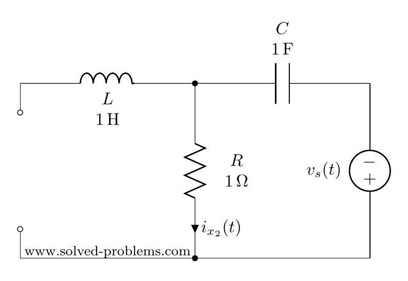


As the inductor branch is open, this is a very simple circuit with three elements in series:  ,
,  and
and  . Therefore,


(why  ?)
?)
Now that we have determined both  and
and  in time domain, we can go ahead and add them up to find . Please note that we could not add and
  because they are not phasors with the same frequency.

Solve the circuit by mesh analysis and find the current and the voltage across  .
.
There are four meshes in the circuit. So, we need to assign four mesh currents. It is better to have all the mesh currents loop in the same direction (usually clockwise) to prevent errors when writing out the equations.
(more…)

Determine the stability of the system whose characteristics equation is:
 .
.
All coefficients are positive and non-zero; therefore, the necessary condition for stability is satisfied. Let’s write the Routh array:
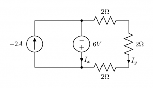
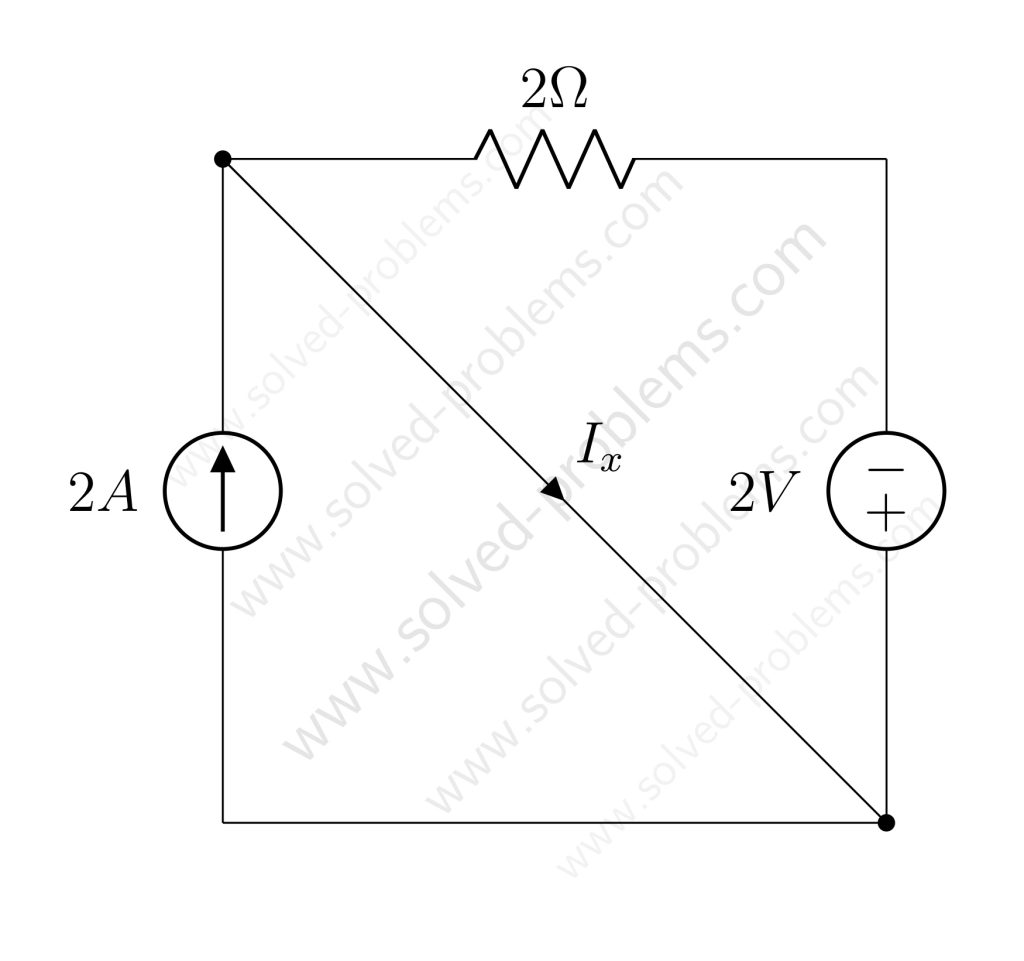
Find and  :
:

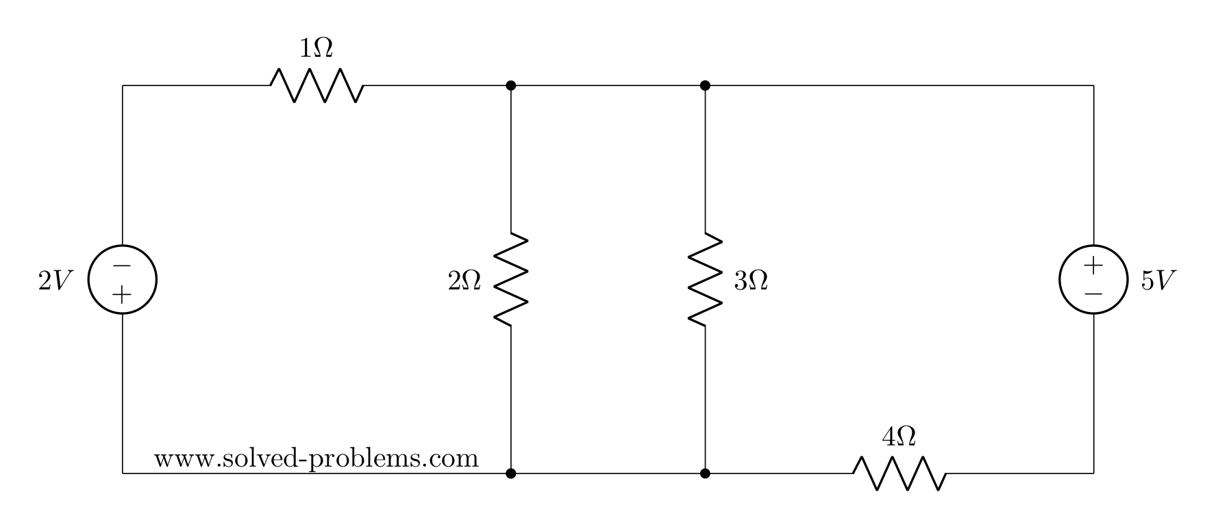
Three resistors are in series and their equivalent,  , is parallel with the voltage source. So, according to the Ohm’s law:
  . The negative sign comes from the direction .
Applying KCL at the bottom node:
 .
.
The lucky winner of the Electrical Circuits Contest #1 is Kunal Marwaha from UC Berkeley. I would like to say thank you to all participants and I am thinking of holding contest #2 soon. Kunal, congratulations and soon you will receive the prize by Paypal.
Determine the driving-point impedance of the network at a frequency of  kHz:
kHz:
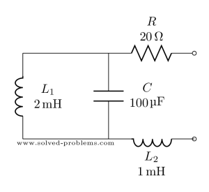
Lets first find impedance of elements one by one:
The resistor impedance is purely real and independent of frequency.