Find the total energy stored in the circuit. Fig. (1-28-1) – The circuit
Solution
The circuit contains only dc sources. Recall that an inductor is a short circuit to dc and a capacitor is an open circuit to dc. These can be easily verified from their current-voltage characteristics. For an inductor, we have . Since a dc current does not vary with time, . Hence, the voltage across the inductor is zero for any dc current. This is to say that dc current passes through the inductor without any voltage drop, exactly similar to a short circuit. For a capacitor, the current-voltage terminal characteristics is . Voltage drop across passive elements due to dc currents does not vary with time. Therefore, and consequently the current of the capacitor is zero. This is to say that dc current does not pass through the capacitor regardless of the voltage amount. This is similar to the behavior of an open circuit. Please note that unlike dc current, ac current passes through capacitors in general. (more…)
Solution
I. Contribution of the voltage source:
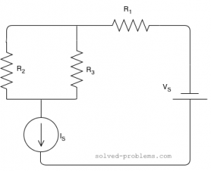
We need to turn off the current source by replacing it with an open circuit. Recall that we do not turn off dependent sources. The resulting circuit is shown below. (more…)
Determine and using the superposition method. Solution
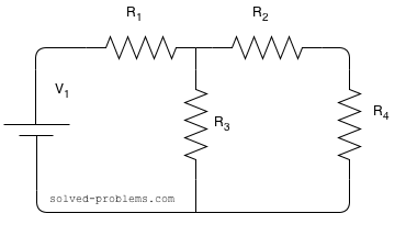
I. Contribution of the voltage source:
To find the contribution of the voltage source, other three sources should be turned off. The voltage source should be replaced by short circuit. The current source should be replaced with open circuits, as shown below. (more…)
Turning off a source, which is usually used in solving circuits with superposition method, means setting its value equal to zero. For a voltage source, setting the voltage equal to zero means that it produces zero voltage between its terminals. Therefore, the voltage source must insure that the voltage across two terminals is zero. Replacing the source with a short circuit can do that. Thus, voltage sources become a short circuit when turned off.
For a current source, setting the current equal to zero means that it produces zero current. Therefore, the current source must insure that no current flows through its branch. An open circuit can do that. Hence, to turn off a current source it should be replaced by an open circuit.
How about dependent sources? The voltage/current of a dependent source is dependent on other variables of the circuit. Therefore, dependent sources cannot be turned off.
 ,
,  ,
,  ,
,  ,
, ,
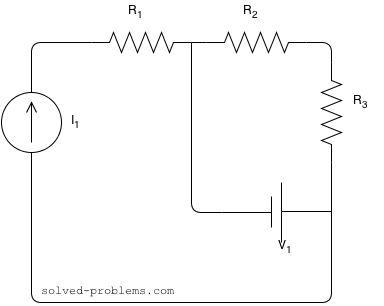
, is in series with the current source; therefore, the same current passing through it as the current source:
 and
and  using voltage division rule.
 ,
,  ,
,  ,
,  and
and 
 are parallel. So the voltage across
 . Since a dc current does not vary with time,
  . Hence, the voltage across the inductor is zero for any dc current. This is to say that dc current passes through the inductor without any voltage drop, exactly similar to a short circuit. For a capacitor, the current-voltage terminal characteristics is
  . Voltage drop across passive elements due to dc currents does not vary with time. Therefore,
  and consequently the current of the capacitor is zero. This is to say that dc current does not pass through the capacitor regardless of the voltage amount. This is similar to the behavior of an open circuit. Please note that unlike dc current, ac current passes through capacitors in general.
 .
.
 load as shown in Fig. (1-27-2).
 .
.
 load as shown below.
 ,
,  and
and  using the superposition method.
 voltage source:
 and
and  using the superposition method.
 voltage source:
 voltage source should be replaced by short circuit. The current source should be replaced with open circuits, as shown below.