Use nodal analysis method to solve the circuit and find the power of the  – resistor.
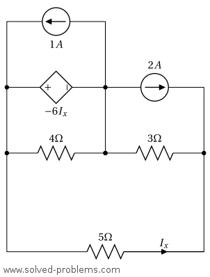
I. Identify all nodes in the circuit.
The circuit has 3 nodes:

II. Select a reference node. Label this node with the reference (ground) symbol.
The node in the middle is connected to 5 nodes and is the node with the largest number of elements connected to it. Therefore, we select it as the reference node of the circuit.
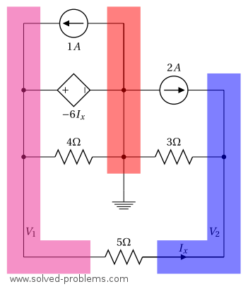
III. Assign variables for unknown node voltages.
We label the remaining nodes as shown above.  is connected to the reference node through a voltage source. Therefore, it is equal to the voltage of the dependent voltage source:
  .
.
IV. Incorporate dependent sources.
If there are dependent sources in the circuit, write down equations that express their values in terms of node voltages.
The voltage of the dependent voltage source is  . We should find this value in terms of the node voltages.
  is the current of the
  – resistor. The voltage across the resistor is
  . You may ask why not
  . Well, that is also correct; the voltage across the resistor is either or depend on which terminal we choose to be the positive one. In this circuit, we are going to use this voltage drop to determine . We prefer to use simply because is the voltage of the terminal that entering from. Therefore, the Ohm’s law can be applied in the simple form of
  . By using the voltage drop , we have
V. Apply Kirchhoff’s Current Law (KCL).
Node of :
Because there is a voltage source in this node, there is no advantage in writing a KCL equation for this node. All we need to do is to use the voltage of the dependent voltage source and its relation with other node voltages:

Node of  :
:

VI. Handle super-nodes.
There is no super-node in this circuit.
VII. Solve the System of Equations.
Substituting  ,
,

VIII. Determine Additional Variables. The power of the -resistor is

Download the Circuit File
To download the LTspice circuit file for your own simulations, click the link below.Please remember to unzip the file after downloading to access the .asc file for your simulations:

Leave a Reply