Find Equivalent Impedance – AC Steady State Analysis

Determine the driving-point impedance of the network at a frequency of 2kHz:

Determine Impedance

Solution

Lets first find impedance of elements one by one:

Resistor R

The resistor impedance is purely real and independent of frequency.

Z_R=R=20 \Omega

Inductors L_1 and L_2

The inductor impedance is purely imaginary and directly proportional to frequency:

Z_{L_1}=j\omega L_1

We need to find the impedance in 2kHz. Therefore:

\omega=2 \pi f=2 \times \pi \times 2000 = 12566 \frac{rad}{s}

Z_{L_1}=j\omega L_1= j \times 12566 \times 0.002=j25.132 \Omega

Z_{L_2}=j\omega L_2= j \times 12566 \times 0.001=j12.566 \Omega

Capacitor C

The capacitor impedance is purely imaginary and inversely proportional to frequency:

Z_C=\frac{1}{j\omega C}= \frac{1}{j \times 12566.4 \times 0.0001}=\frac{1}{j \times 1.2566}

To get the standard representation of complex numbers, we need to bring j to numerator and this can be done by multiplying by j:

Z_C=\frac{j}{j \times j \times 1.2566}=\frac{j}{-1 \times 1.2566}=\frac{-j}{1.2566}=-j0.796 \Omega

Note how capacitor acts in this frequency. The value of impedance is less than 1 \Omega. Compare this value to values of other components. It is almost equivalent to a short circuit!

Equivalent Impedance

Let’s replace the values in the circuit:
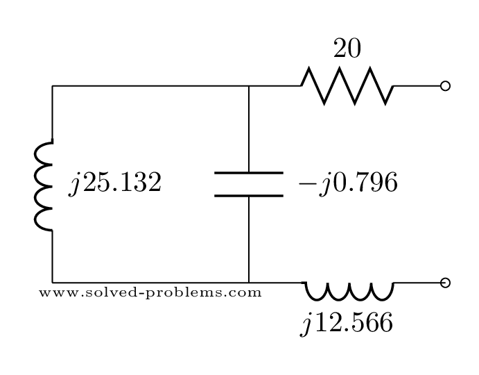
Impedance equivalent circuit

j25.132 and -j0.796 are parallel.

j25.132 || -j0.796=\frac{j25.132 \times (-j0.796)}{j25.132 + (-j0.796)}=\frac{20}{j24.336}=-j0.823

One interesting point here is that unlike pure resistive circuits where the equivalent resistance of parallel elements is always less than the resistance of each element, the value of the equivalent impedance of parallel elements can be greater than the value of the impedance of elements. Here the capacitor impedance value is 0.796 but the equivalent impedance, 0.823, is higher.

Simplified impedance equivalent circuit

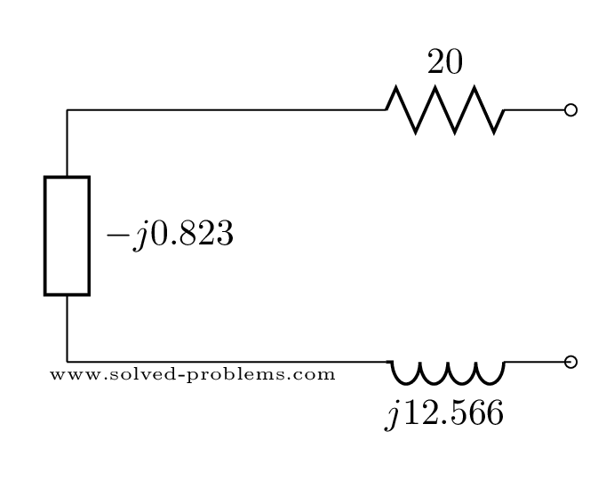
Three components are in series. Therefore:
Z=20+(-j0.823)+j12.566=20+j(-0.823+12.566)=20+j11.743=23.193 \angle 30^{\circ} \Omega

Now, determine the impedance at 20Hz and 200kHz and share it with others below in comments section.

Master Nodal Analysis with ease!

I’ll send you a simple yet powerful guide to help you tackle circuit problems effortlessly.

Get the free eBook by subscribing below.

    We respect your privacy. Unsubscribe at any time.

    Comments

    8 responses to “Find Equivalent Impedance – AC Steady State Analysis”

    1. Samson Dharmaraj Avatar

      Determine the driving-point impedance of the network at a frequency of 2 kHz:
      Zc was calculated as -j0.796 Ohms but the correct calculation is -j0.0796 ohms
      The final answer will be 20+j12.52 = 23.6 with angle of 32.05.
      Thanks

      1. Manoj Avatar
        Manoj

        Please explain the last step, converting j12.52 to degree.
        Thank you.

    2. Nick Avatar
      Nick

      In solving for the impedance of the Capacitor, you use .0001 as the value for 1000uF.

    3. Alec Poulin Avatar
      Alec Poulin

      The question asks for a 1000 µF (1 mF) capacitor, but the solution is made with a 100 µF (0.1 mF) capacitor.

      1. Yaz Avatar

        Thank you for reminding. It is fixed now.

    4. Aditya Avatar
      Aditya

      Thanks sir for the content you have provided which really help me to improve my concept…

    5. Marco Polo Avatar
      Marco Polo

      Really nice to see the different steps. Thanks!

    6. Abdullahi Suleiman Ingawa Avatar
      Abdullahi Suleiman Ingawa

      Why you didn’t drop the solution

    Leave a Reply to Yaz Cancel reply

    Your email address will not be published. Required fields are marked *