Reference Node
In circuits, we usually label a node as the reference node also called ground and define the other node voltages with respect to this point. The reference node has a potential of  by definition. The following symbol is used to indicate the reference node:

As mentioned, the selection of the reference node is arbitrary. However, a wise selection can make the solving easier. As a general rule, it is usually chosen to be
- a node with largest number of elements connected to it, or
- a node which is connected to the maximum number of voltage sources, or
- a node of symmetry.
Node Voltages
The voltage drop from a node to the reference node (ground) is called the node voltage. To keep definition simple, node voltages are usually defined with positive polarities.
Let’s find label node voltages in the following circuit:
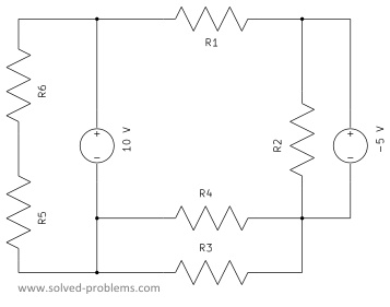
The circuit has 5 nodes:
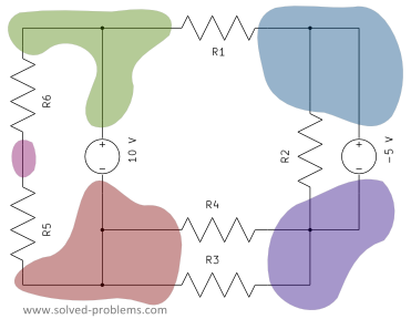
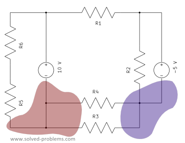
Two of the nodes have 4 elements connected to them. These are the best candidates to be reference point.
Let’s label one as reference node.
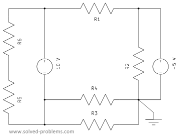
Now, we define node voltages for the remaining nodes. These node voltages represent the voltage between the node and the reference.
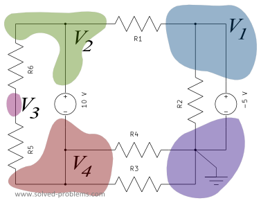
When there is a voltage source between a node and the reference node, the node voltage corresponds exactly to the voltage of the voltage source. In our example, we have two node voltages. The  voltage source is placed between the reference and the node labeled as
  . Therefore,
  .
.
If there is a voltage source between two nodes, the difference between the corresponding node voltages equals to the voltage of the source. In our example, the  voltage source is located between nodes labeled by
  and
and  . Therefore,
  . It is important to note that voltage of the positive node minus the one of negative node is equal to the voltage of the source. KVL can be used to show this:
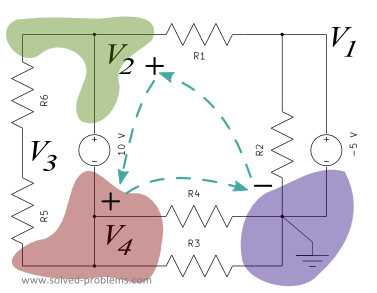
KVL around the loop:  . Recall that the reference node is always defined to be the negative polarity of all node voltages.
Leave a Reply