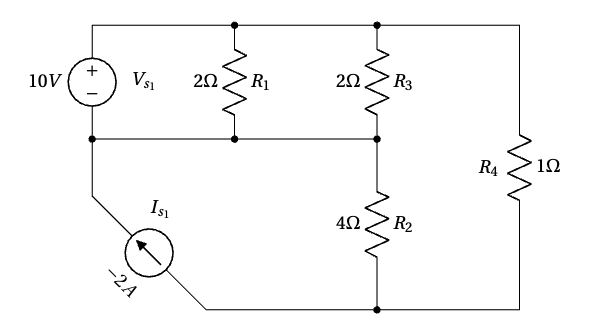
Solve the circuit using nodal analysis and determine the power of  .
.
Solution
I. Identify all nodes in the circuit. The circuit contains 3 nodes, as illustrated below.
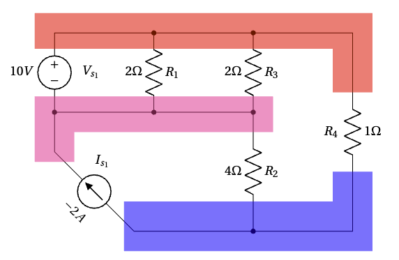
II. Select a reference node. Label this node with the reference (ground) symbol.
In this circuit, two nodes are connected to the voltage source, making them suitable candidates for the reference node. We will choose the node connected to the negative terminal of the voltage source, which allows us to directly relate the voltage of the other node to the voltage source.
wp_stand_ad_camp_2
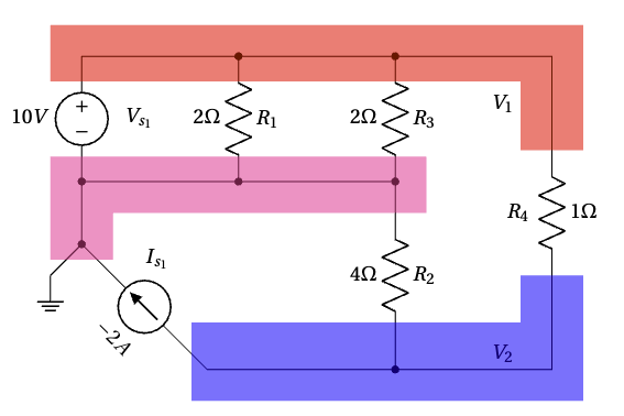
III. Assign variables for unknown node voltages. We label the remaining two nodes as  and
and  , as shown above.
IV. Incorporate dependent sources. There are no dependent sources in this circuit.
V. Apply Kirchhoff’s Current Law (KCL).
For node , since it is connected to the reference node via a voltage source, we can directly state that:

For node , we can write the KCL equation as follows:

Substituting  and
and  ,
,  :
:

Solving this equation yields:

VI. Handle super-nodes.
There is no super-node in this circuit.
VII. Solve the System of Equations.
All node voltages already determined.
VIII. Determine Additional Variables. Calculate the power of .
The power supplied by the current source can be calculated as:

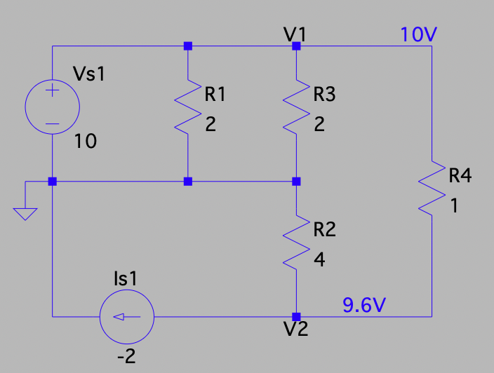
LTspice Analysis
Below is the LTspice schematic for the circuit.
Download the Circuit File
To download the LTspice circuit file for your own simulations, click the link below.Please remember to unzip the file after downloading to access the .asc file for your simulations:
Leave a Reply